Signal Processing with AMD-Xilinx Kria K24 and KD240
Author
Nikil Thapa
Senior FPGA Design Engineer
LogicTronix Technologies

Overview
This article provides brief design details on the implementation of the AMD-Xilinx FIR Compiler IP and a demonstration of the EEG signal filtration. For demonstration purposes, an EEG signal dataset, sampled at 1kHz (can also work for 4kHz to 8kHZ EEG signals to), has been used. To filter the EEG signal, a Low Pass Filter (LPF) with a cut-off frequency of 100Hz and 33 filter taps has been designed. The design has been compiled using the Vitis tool version 2023.2 and targeted for AMD-Xilinx Kria KD240, which consists of K24 SoM.
For the complete EEG signal processing on AMD-Xilinx FPGA , we have two approach of solution:
- AMD-Xilinx VIVADO IP Design and Baremetal/Linux Application – quicker , adaptive design and user friendly application
- Custom RTL IP core flow – optimized and resource efficient design
In this article we are providing steps and methods for VIVADO IP design flow and Baremetal Application based EEG signal processing approach based on MPSoC variant of FPGA, Kria KD240 with K24 SoM. For custom RTL approach, please contact us by filling up form below at the footer of this article.
Vivado Block Diagram
To implement the FIR filtration operation, a Vivado block diagram has been created that consists of major IP blocks such as FIR compiler, AXI-DMA, and Zynq UltraScale+ Processing IP blocks, and their connections are illustrated as shown in the picture below.
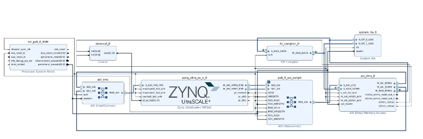
Figure 1. Hardware Design using Vivado IPI
This type of design makes it possible to read EEG data from DDR memory, feed data into the FIR IP, perform a filtering operation, and write the filtered signal data back into the DDR memory again. To achieve real-time memory data read and write operations, the AXI-DMA has been configured with a read and write channel customization. Similarly, the AMD-Xilinx FIR Compiler IP is capable of performing real-time filtration operations and supports both static and dynamic FIR coefficient loading. However, this demonstration is based on the static FIR coefficient loading method, as illustrated in the following FIR customization window picture, where the FIR filter coefficients are placed in the coefficient vector field.

Figure 2. FIR IP customization with Static FIR coefficients
The resource utilization of this design is significantly low, so we can have multiple channel of similar signal processing pipeline inside single Kria K24 or SoM FPGA.
Software Application
This section gives an overview of a bare-metal application created in the Vitis SDK IDE and a Python application. A bare metal application has been created to deploy on PSU_CORTEX A53_0 APU, while a Python application has been created to run on the host PC and has a major function to facilitate loading and capturing the EEG data and filtered data, respectively, between the board and the host pc through UART communication. The bare-metal application uses embedded C language, where AXI DMA is configured in a flow that reads the EEG data from DDR memory and feeds it into the FIR IP in real-time. On the other hand, it receives the filtered EEG data from the FIR IP and writes it into DDR memory. For demonstration purposes, 200 samples of EEG data have been considered.
The following pictures illustrate the snapshots of the bare metal and Python application code.

Figure 3. Bare-metal Application Code Snippet

Figure 4. Python Application Code Snippet
Design Run
The bare-metal application is deployed on the Kria KD240 board while the Python application is launched on the host PC. They both run in parallel in real-time.

Figure 5. Bare metal Application running on the Kria KD240 Board
The Python Application, running on the host PC, reads EEG data samples from the file and sends them to the board, while a bare metal application running on the board receives the data and stores them into the memory, and then AXI DMA is configured. On the other hand, the bare-metal application sends back filtered data samples to the host PC, where the Python application captures the data into an output file.
The following pictures illustrate the snapshots of the unfiltered EEG input data file and the filtered EEG output data file, respectively, loaded and captured by the Python application.

Figure 6. The contents of the input file before filtering. The EEG data are represented in hexadecimal format

Figure 7. The contents of the output file after filtering in signed integer format, captured by a Python Application
For the visual illustration, the matplot package in the Python application has been used to plot the Time and Frequency Response of both unfiltered and filtered EEG signal data, as shown in the picture below.

Figure 8. Time and Frequency Response Plots for input and output EEG signal Data using a Python Application
As we implemented a FIR filter to stop frequency components above 100Hz, we can clearly see from the above plots that frequency components above 100Hz are completely stopped and the filtration operation is working as expected in real-time. Similarly, we can implement different FIR filters to do a variety of signal processing tasks further.

Figure 9. Loading and Capturing of EEG data by the Python application, seen in the Linux Terminal
The above picture illustrates the loading of unfiltered EEG data and the capturing of Filtered EEG data by the Python application.
This article completes here!
Kudos to team members, Abhidan Jung Thapa (R & D Lead) and Rajesh Kumar Mahato (FPGA Design – Engineer (Jr.)) for collaboration on EEG Signal Processing , Filter Design techniques and RTL Implementations.
What coming?
EEG Signal Classification with AI/ML techniques on Kria K24 SoM – an Edge AI Solution for Medical Application.
Do you want to perform EEG, RF or other Signal Processing and implementing AI/ML techniques on Signals?
If then, please fill up the following form: