Histogram calculation with AI Engine in Versal VCK190
Author
Sanam Shakya
Senior Embedded and Algorithm Engineer
LogicTronix Technologies

Overview
This tutorial shows steps to accelerate the computation with the AI Engine in AMD Versal VCK190 Evaluation Kit. For this threaded histogram algorithm is implemented by dividing the input into N=4 partitions. Each input partition is assigned to different tiles in the AI Engine.
After histogram is calculated, output from each tile is added together to obtain the final histogram.
Requirements
- AMD Versal™ AI Core Series VCK190 Evaluation Kit
- AMD Vitis™ Unified Software Platform 2025.1
- Kernel Image, Rootfs and SDK [Versal Common] – LINK

Test Setup
Algorithm for Histogram Calculation
Histogram is the data reduction algorithm where it is computed by scanning through the input data and recording how many times a scanned value appears in the input data. Here is the simple sequential c code for calculating the histogram of the input data array :
| for( int i = 0; i < DATA_SIZE; ++i) { bin[data[i]]++; } |
Here for loop walks through the data array and increments the count of each value. So the bin array stores the histogram result.
To parallelize the histogram algorithm, we divide the computation by partitioning the input data into multiple processing elements called tiled computation. We bread the work into chunks called tiles and each tile operates independently and later combines the results.
Pictorial representation of tiled histogram algorithm in AI Engines:

Block diagram – Tiled Histogram Algorithm
For testing, input image data in grayscale format is stored in input.h header file and output is tested with pre-computed histogram and further printed on the console. Here is the test input image and corresponding histogram.

Fig. Test Image and Corresponding Histogram
Implementation of the tiled histogram kernel is divided into various components in Vitis Unified IDE. Here are the steps which we will follow to create complete system project to run the implementation on linux operating system :
- Create an AI Engine components application project
- Adding PL kernels for input and output
- System Integration
- Creating PS host application
- Packaging system components and creating SD card image
- Running and testing the host application
Before starting the above steps get the source files for AI engine, PL and host application component from the following github link : https://github.com/LogicTronixInc/vck190-AIE-Histogram-computation
Download or clone the files and folders from the above link. We will be using code files and config from the above link.
Step 1 : Create an AI Engine components application project
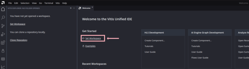
- Open Vitis Unified IDE by loading the Vitis environment variable and running `vitis` in the terminal.
- Click on Set Workspace to open the new workspace for this tutorial. For this tutorial, we have used “aie_sys_histo_design_ws” as the workspace name.
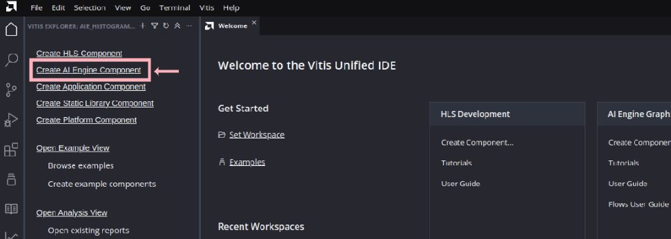
- Next to start the AI Engine component add the AI Engine component by clicking “Create AI Engine Component ” in Vitis Explorer present in the left hand side of Vitis Unified IDE.
- Assign name and location for the new component. Here we are assigning the Component name as : “aie_sys_histo_design_aie” and location as the workspace created in step 2.

Click “Next” to go to the next step of adding source files. We are going to add our source and data files manually so skip the adding source file by clicking “Next” again.
- In Hardware selection, select the VCK190 base platform (xilinx_vck190_base_002320_1)
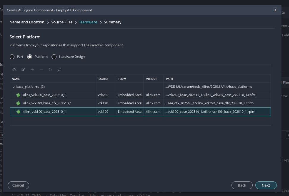
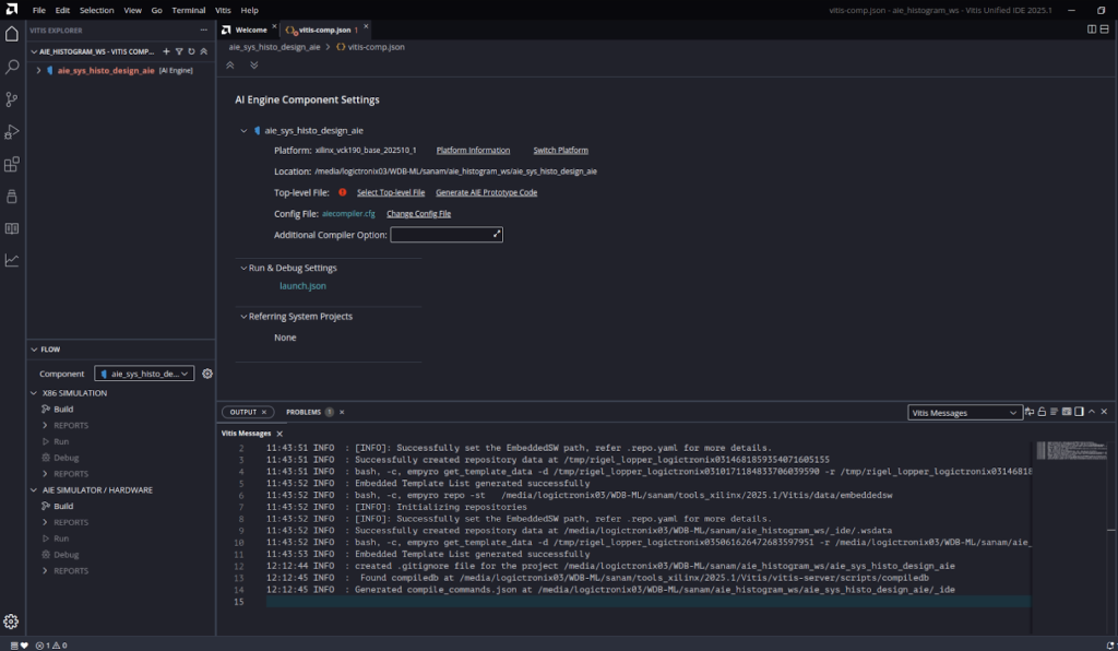
Click “Next” to go to the summary page. After verifying the summary click “Finish” to finish the create component wizard. Here is the status of Vitis Unified IDE after following above steps :
- Expand the AI Engine component int the Vitis Explorer and add new data and src folder in the “Source”
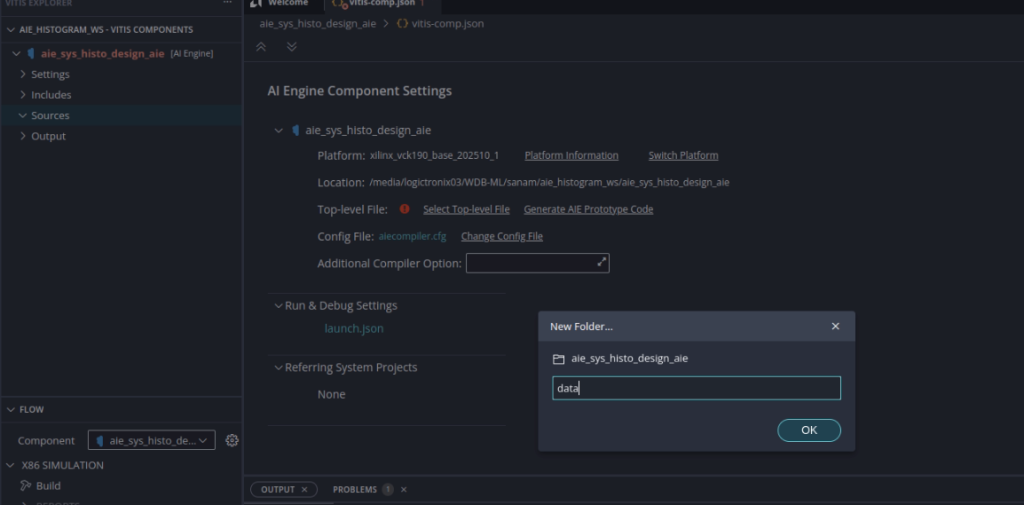
- Now add the AI Engine Kernel and graph code into source folder by right clicking the “Sources/src” and “import”. You can browse the “vck190-AIE-Histogram-computation/aie/src” directory and select multiple files to import the files.

Similarly import content of “vck190-AIE-Histogram-computation/aie/data” into the data folder.
Note: Each AI Engine Component project consists of following files :
I. Kernel header and Kernel Source files
These are the computation code running in the AI Engine processor.
In this project we have three kernel files :
- Histogram_kernel.cc
- Histo_accumulator.cc
- Histo_accumulator_stream_out.cc
II. Graph header and source file
Graph header file is the main file which consists of a graph of components. It consists of instances of kernels and connection between kernel components and interfaces. And the source file consists of an instance of Graph and commands api to simulate the graph in Vitis aiesimulator.
In this project we have graph header and source file as :
- Histogram_graph.h
- Histogram_graph.cpp
- Before building the AI Engine component project, assign a top level file by clicking “Select Top Level File” in the “vitis_comp.json”.

And select “histogram_graph.cpp” from the “src” directory as the Top level file.

Vitis unified IDE provides two build environments for the AI Engine Component project :
X86 simulation and AI Engine Simulation/Hardware build flow environment. These are available at “Flow” explorer located at the right bottom of Vitis unified IDE.

- First, build is done for testing and verifying the algorithm implemented in kernel. So click the “Build” in X86 SIMULATION.
If there is no error in the project, the build completes successfully. One can check the status of the build in the “Output” console.
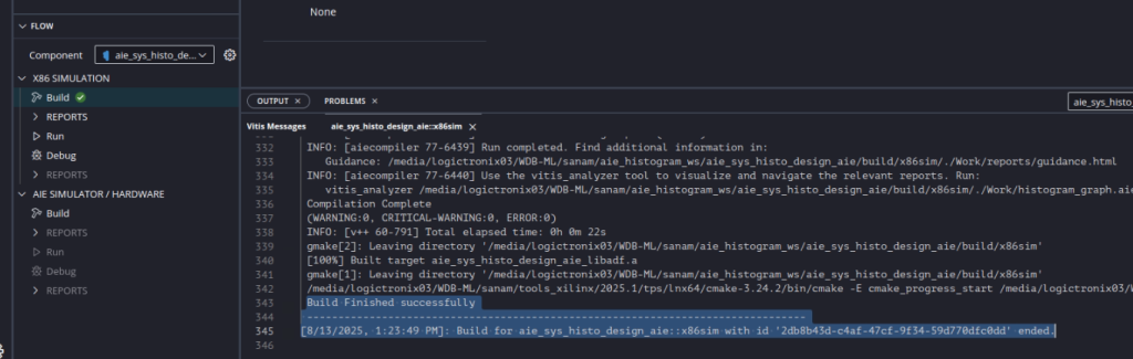
Next one can check “Reports” to view the pictorial representation of the graph.

- Next run the x86 simulation in the “Flow navigator” by clicking the “Run” under “X86 Simulation”.

After simulation is completed, one can check the output of simulation in “Vitis Component” navigator in “Output” -> x86Simulator_output->data->acc_output2.txt file
One can compare the output with the golden file to test the output.

Once the kernel code is verified and tested in x86 simulation. Next step is to build the project for AIE simulation / Hardware build.
- Before the build increase the Stack Size and Heap Size to 2048 by setting the values in “aiecompiler.cfg” located in “Settings” under Vitis component.

- Build the AIE simulation / Hardware by clicking “Build” in “AIE simulation / Hardware” in Flow Navigator.
After the successful build, detail reports are generated for Tile utilization in summary report. It also generates graphical representation of kernel implementation in AI Engine tiles in the Array report.
One can check summary and Array report for getting the utilization and kernel implementation in AI Engine Tiles.


In above tile implementation, kernel and corresponding tile number is shown with data flow. In above implementation, Tile and kernel mapping is done by assigning :
K2 to Tile 23,0
K3 to Tile 24,0
K1 to Tile 25,0
K0 to Tile 26,0
Histo_acc1 to Tile 23,1
Histo_acc2 to Tile 24,1 and
Histo_acc0 to Tile 25,1.
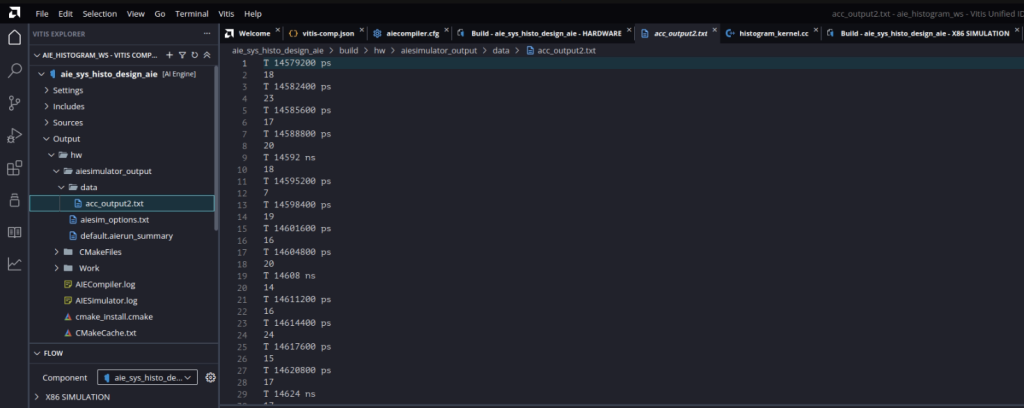
- Next run the AI Engine system C based simulation by clicking the Run under AIE SIMULATOR / HARDWARE in flow navigator.

Corresponding output of the simulation is created at Output -> hw -> aie_simulator -> data -> acc_output2.txt
This ends the AI engine component build. Next we will be adding PL kernels to stream input and output from the AI engine graph.
Step 2 : Adding PL kernels for input and output
In this project HLS kernels are used as a bridge between memory and AXI4-Stream interface to input and output data from memory.
Two HLS kernels are used. mm2s kernel is used to read data from memory and transfer stream to the AI Engine graph. s2mm HLS kernel is used to receive output stream from AI Engine array and write to the memory.
- In the Vitis Unified IDE click File -> New Component -> HLS
- Name the first component aie_sys_histo_design_mm2s and click Next.
- In the Configuration File page, keep the default settings (Empty File) and click Next
- In the Add Source Files page, add the file mm2s.cpp from the vck190-AIE-Histogram-computation/pl folder.

- In the same page, set the mm2s function as the top function (click Browse and select mm2s)


- In the Select Platform Page select vck190 base platform and click Next.

- In the Edit Settings page select Vitis Kernel Flow Target under flow_target and Generate a Vitis XO under package.output_format and click Next
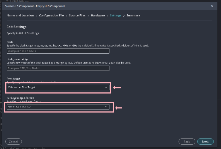
- Click Finish
- Repeat steps 1 to 8 to create another HLS component called aie_sys_histo_design_s2mm with the vck190-AIE-Histogram-computation/pl/s2mm.cpp source file
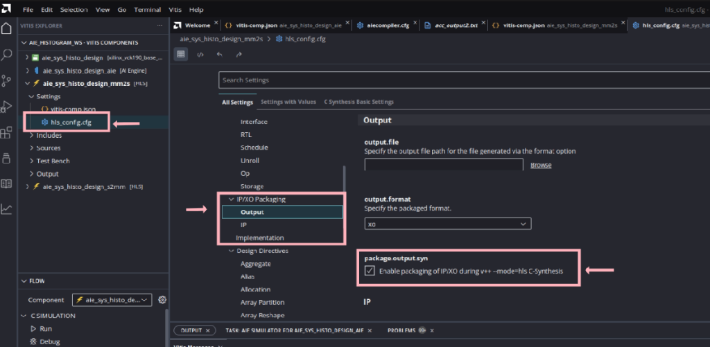
- Open hls_config.cfg in Vitis component navigator and enable the XO package generation by enabling package.output.syn -> Enable packaging
- Then build the HLS components by clicking “Run” in C SYNTHESIS followed by “Run” in Implementation in Flow navigator.

Step 3. System Integration
In this step AI Engine graph, HLS kernels and hardware platform is combined to create the hardware overlay and further system project component is used to create the bootable linux SD card for running on the hardware.
So before setting the system component, get the kernel image, root filesystem and sysroot from petalinux project or for this project we are using the already available build common image available at AMD embedded design tools download page.
- Extract the downloaded file and note the path for following files :
- Kernel Image file : <path to xilinx-versal-common-v2025.1>/Image
- Rootfs file : <path to xilinx-versal-common-v2025.1>/rootfs.ext4
- sysroot : <path to xilinx-versal-common-v2025.1>/sdk/sysroots/cortexa72-cortexa53-amd-linux
- First create a new System Project component by clicking File > New Component > System Project
- Assign aie_sys_histo_design as the project name and click Next.
- In the select Platform page, choose VCK190 base platform (xilinx_vck190_base_002320_1)
- In the Embedded Component Paths page, select the Kernel image path, Rootfs path and sysroot path as you noted down in above step 1.

- Then click “Finish” to end the System Project Component Creation.
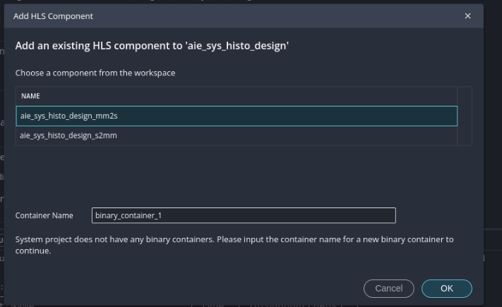
- Open the settings file called vitis-sys.json under aie_sys_histo_design > Settings and click on Add Existing Components in the Components section. Click HLS and select the aie_sys_histo_design_mm2s and aie_sys_histo_design_s2mm components.
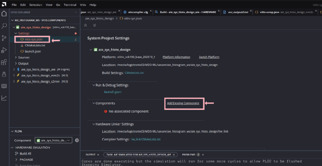
- Click again on Add Existing Components in the Components section at the bottom of the file. Click AI Engine and select the aie_sys_histo_design_aie component.
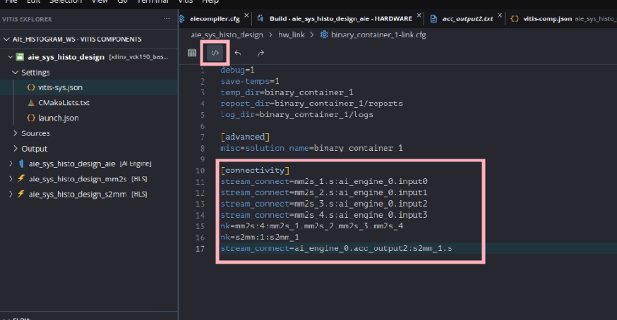
- Now you need to tell the Vitis compiler about the connectivity of the system. This step is done using a configuration file. Still in the settings file vitis-sys.json, under Hardware Link Settings expend binary_container_1 and click on hw_link/binary_container_1-link.cfg

- Update vck190-AIE-Histogram-computation/hw_link/binary_container_1-link.cfg file by first changing view to “Source editor” view and updating the [Connectivity] with following values :
| … [connectivity] stream_connect=mm2s_1.s:ai_engine_0.input0 stream_connect=mm2s_2.s:ai_engine_0.input1 stream_connect=mm2s_3.s:ai_engine_0.input2 stream_connect=mm2s_4.s:ai_engine_0.input3 nk=mm2s:4:mm2s_1.mm2s_2.mm2s_3.mm2s_4 nk=s2mm:1:s2mm_1 stream_connect=ai_engine_0.acc_output2:s2mm_1.s … |
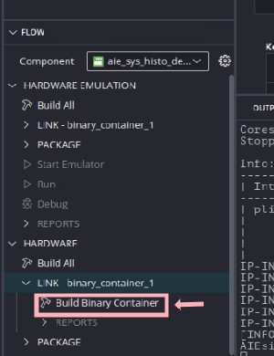
- In the flow navigator, make sure aie_sys_histo_design is selected and click on Build Binary Container under HARDWARE > LINK – binary_container_1. Click OK when asked to build the HLS components. The compilation process takes some time to finish.
After build is completed hardware is generated and can be opened in Vivado.
- You can open the generated the AMD Vivado™ project in <workspace>/aie_sys_histo_design/build/hw/hw_link/binary_container_1/binary_container_1/vivado/vpl/prj/prj.xpr to take a look at the compilation result. You can see that the Vitis compiler added the HLS IP (multiple mm2s_x and s2mm) and connected them to the memory (NOC) and AI Engine IP.

Step 4 : Creating PS host application
- Create a new application by clicking File → New Component → Application.
- Set the name for the application to aie_sys_histo_design_host and click Next.
- Select vck190 base platform (xilinx_vck190_base_202510_1) as the platform and click Next.
- Click Next to go to next page.
- In Sysroot page browse the location of sysroot located at <path to xilinx-versal-common-v2025.1>/sdk/sysroots/cortexa72-cortexa53-amd-linux and click Next.
- We will be adding sources manually so skip the Source Files page by clicking Next and then click Finish to finish the setup steps. This will create aie_sys_histo_design_host application component and be listed in vitis component navigator.
- Now create a “src” folder in aie_sys_histo_design_host -> Sources and import the host code located at vck190-AIE-Histogram-computation/host/src folder.

- Next open CMakeLists.txt located at aie_sys_histo_design_host -> Settings and change the CMAKE_CXX_STANDARD_VERSION to 17

- Next build the project by clicking “Build” in Hardware in the Flow Navigator.

This will build the host application and create an executable.
Step 5 : Packaging system components and creating SD card image
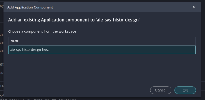
- Open the settings file vitis-sys.json for the aie_sys_histo_design and add host application created in last step by clicking Add_Existing_Component -> Application -> aie_sys_histo_design_host

- Now package the whole system project by clicking Build Package under Hardware -> PACKAGE in the flow navigator.
This will create an SD card image, which can be found at <workspace>/aie_sys_histo_design/build/hw/package/package/sd_card.img. This is the linux image which is used in the next step to boot and test the system.
Step 6 : Running and testing the host application
- Set up your board with proper connection of power cable, UART USB cable, and set the BOOT MODE to SD Boot.
- Burn the sd card image located at <workspace>/aie_sys_histo_design/build/hw/package/package/sd_card.img to sd card using flashing tool like Balena Etcher.

- Insert the SD card to the memory card slot into VCK190 board and switch on the power and open the serial terminal port usually /dev/ttyUSB1 with baudrate of 115200. During first boot you need to update the password with user login as “petalinux”

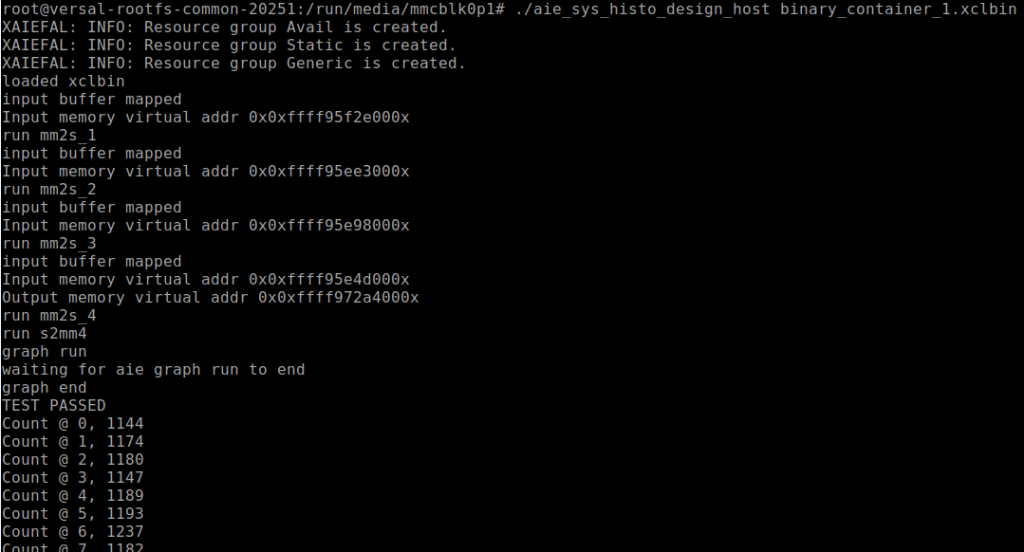
- Now run the application by running following commands :
| sudo -i cd /run/media/mmcblk0p1 dmesg -n 4 export XILINX_XRT=/usr ./aie_sys_histo_design_host binary_container_1.xclbin |

This will run the histogram calculation for an array with 640×480 elements and test with the precomputed histogram golden result and print the bin count in the console.
Summary
- In this tutorial, we explored programming flow for integrating AI Engines, Programmable Logic (PL) and host application in Versal VCK190 Evaluation Kit with the tiled Histogram computation algorithm. This is the just minimal example to get familiar with the Versal AI Engine kernel programming.
- For full utilization of this heterogeneous system one can implement vector computation algorithms for Neural Networks, Sparse matrix computation, Digital signal processing and Image processing.
Thank you for going through this tutorial!
Kudos to Abhidan Jung Thapa (Research & Development Lead- LogicTronix) for his input on AIE , Versal Architectural design and support on implementation and testing phases!